Views: 0 Author: Site Editor Publish Time: 2026-09-04 Origin: Site

Evaluating a waterjet cutting machine based solely on its maximum linear traverse speed is a common procurement trap. Buyers often fixate on straight-line velocity specifications while ignoring actual part-cycle times. This oversight creates massive production bottlenecks on the shop floor.
A fundamental tension exists between maximizing production throughput and maintaining strict edge quality tolerances. Raw speed alone cannot guarantee efficient production. You must balance optimal acceleration, consistent pump pressure, and precise abrasive control. Pushing a machine beyond its dynamic capabilities leads to severe V-taper, visible striations along the cut edge, and ultimately, rejected parts.
This guide provides a technical evaluation framework for assessing waterjet speed factors. We cover everything from advanced pump technology and machine kinematics to multi-head configurations. You can use this data to specify the exact system required for your specific production volume and material density.
Acceleration Trumps Linear Speed: For most complex part geometries, a machine’s ability to accelerate and decelerate into corners dictates true cycle time more than its maximum straight-line cutting speed.
Pressure Multiplies Velocity: Upgrading from a 60,000 PSI to a 90,000 PSI pump increases the water stream velocity (up to 2.5 times the speed of sound), significantly reducing cut times and abrasive consumption per part.
Process Mode Dictates Baseline Speed: Pure waterjet cutting (for soft materials) operates at vastly higher speeds than abrasive waterjet cutting (for metals and composites), making material density the ultimate baseline for speed expectations.
Edge Quality Dictates Feed Rates: Cutting speed is not static; it must be dynamically scaled against the desired edge finish (typically graded Q1 through Q5) to prevent structural deflection and taper.
Hardware Scaling is Often More Efficient: Deploying a multi-head automatic waterjet cutting system often yields higher throughput for high-volume runs than attempting to maximize the cutting speed of a single cutting head.
True production speed relies on floor-to-floor time. This metric encompasses the entire operational cycle on the shop floor. Focusing only on the cutting feed rate provides an incomplete picture. A machine might cut exceptionally fast in a straight line. However, if it takes too long to transition between pierce points, overall throughput drops. You must evaluate the entire process cycle to understand true machine efficiency.
A standard floor-to-floor cycle consists of several distinct phases that impact total speed:
Material Staging: The time required to load the raw plate onto the cutting bed and secure it.
Head Positioning: The rapid traverse movement from the home position to the first pierce point.
Piercing Cycle: The dwell time required to penetrate the material before linear movement begins.
Profile Cutting: The actual linear and radial movement along the programmed toolpath.
Rapid Transitions: The non-cutting movements between separate parts nested on the same sheet.
Unloading: Removing the finished parts and clearing the scrap skeleton from the tank.
Maximum traverse speed measures how fast the gantry moves in a straight line. Machine kinematics measure acceleration and deceleration capabilities. These are expressed in G-forces. High linear speed looks impressive on a specification sheet. High G-force acceleration actually dictates real-world performance. A heavy gantry requires significant time to reach top speed. It also requires time to slow down.
A machine with superior acceleration reaches optimal cutting feed rates much faster. This dynamic responsiveness directly reduces cycle times. Consider a gantry weighing 1,500 pounds moving at 1,000 inches per minute. The servo motors must generate massive torque to stop that mass precisely on a coordinate. If the drive system lacks stiffness, the gantry overshoots. The machine must then pause to let the vibrations settle before piercing. These micro-delays accumulate rapidly over a full sheet of nested parts.
Frequent starting, stopping, and tight cornering neutralize high linear speeds. Intricate profiles demand constant velocity changes. The drive system must respond instantly to these directional shifts. A machine cutting a complex gear profile rarely reaches its maximum linear speed. It spends most of its time accelerating out of one curve and decelerating into the next.
Drive system responsiveness becomes the primary evaluation metric here. Sluggish drives cause the cutting head to dwell too long in corners. This dwelling washes out the material. The high-pressure stream erodes too much material on the inside radius, ruining part tolerances. Fast acceleration pulls the stream out of the corner before excess erosion occurs.
Higher pump pressure directly translates to higher kinetic energy. Water pressurized to extreme levels forces its way through a tiny jewel orifice. This restriction accelerates the water stream. The stream velocity can reach up to 2.5 times the speed of sound. This immense kinetic energy transfers to the abrasive particles in the mixing chamber. Faster particles erode material much quicker. Pressure dictates the fundamental speed limit of the cutting process.
Comparing 60,000 PSI systems to 90,000 PSI systems reveals stark differences in operational capability. Upgrading to 90,000 PSI often yields 30% to 50% faster cutting speeds. The higher velocity stream cuts a narrower kerf. It removes material more efficiently. This speed increase significantly boosts daily part output. It allows operators to process thicker materials without drastically reducing feed rates.
Pump Pressure | Stream Velocity | Relative Cutting Speed | Optimal Material Thickness |
|---|---|---|---|
60,000 PSI | Mach 2.0 | Baseline (100%) | Up to 2 inches |
90,000 PSI | Mach 2.5 | 130% - 150% | Up to 6 inches |
Pump technology also impacts speed stability. Intensifier pumps use hydraulic cylinders to pressurize water. Direct drive pumps use a mechanical crankshaft. Advanced pressurizing pumps minimize pressure pulsation. Consistent pressure ensures a steady stream velocity. It prevents micro-stutters during the cutting process. A smooth, continuous stream maintains a constant erosion rate. This stability allows the CNC controller to maintain higher average feed rates without risking cut loss.
Pure waterjet cutting handles soft materials like foam, rubber, and gaskets. Abrasive waterjet cutting tackles hard materials like steel, stone, and titanium. Pure water cutting operates at vastly higher speeds. The absence of abrasive mixing eliminates a major restriction in the cutting head. Pure water streams slice through soft materials almost instantly.
Abrasive cutting requires time for the particles to erode the material matrix. The water merely acts as a carrier for the garnet. You cannot force abrasive cutting to match pure water speeds. Material density establishes the ultimate baseline for your speed expectations. Attempting to cut half-inch steel at pure water speeds will simply deflect the stream and fail to penetrate the plate.
Abrasive feed rates directly influence cutting speed in hard materials. Increasing the volume of garnet entering the mixing chamber generally increases the erosion rate. More cutting edges hit the material per second. This allows the operator to increase the machine feed rate accordingly. However, this relationship is not infinitely linear.
You eventually reach a point of diminishing returns. Excess abrasive clogs the mixing tube. The water stream cannot accelerate an infinite mass of garnet. Overloading the mixing chamber reduces the overall velocity of the abrasive stream. The cutting speed actually drops. You must find the precise abrasive flow rate that maximizes particle velocity without choking the nozzle. Garnet mesh size also plays a role. An 80-mesh garnet cuts faster but leaves a rougher edge. A 120-mesh garnet cuts slower but provides a smoother finish.
The ratio between the jewel orifice and the abrasive mixing tube is critical. This ratio affects stream density and kerf width. A larger orifice allows more water volume. This requires a larger mixing tube to accommodate the increased flow. A properly matched orifice and mixing tube create a highly cohesive stream. The industry standard ratio is typically 1:3. For example, a 0.010-inch orifice pairs with a 0.030-inch mixing tube.
A cohesive stream concentrates the cutting energy into a tight area. It prevents the stream from flaring out as it exits the nozzle. A tight stream cuts faster and cleaner. It dictates the maximum allowable feed rate. If the stream loses cohesion, the cutting energy dissipates. You must slow the machine down to ensure the stream penetrates the full thickness of the material.
A high-speed CNC waterjet cutting machine relies on robust drive systems. Traditional rack and pinion drives offer reliable performance for standard cutting. Helical rack systems provide smoother motion than straight racks. Ball screw drives provide higher precision for intricate parts but can suffer from whip over long travel distances. Linear motor technology represents the pinnacle of motion control. Linear motors eliminate mechanical contact between drive components. They offer frictionless movement and extreme acceleration capabilities.
Drive stiffness and backlash elimination are paramount. Backlash causes micro-hesitations when the machine changes direction. These hesitations leave visible marks on the cut edge. High stiffness allows for faster cornering without sacrificing precision. The gantry can handle higher G-forces without vibrating. This mechanical stability lets the CNC controller push feed rates higher during complex profile cutting.
Advanced CAM software and CNC block processing speeds dictate dynamic performance. A controller must process G-code incredibly fast. High-node-count geometries contain thousands of tiny line segments. If the controller processes code too slowly, the machine will pause or stutter. These micro-pauses ruin edge quality and inflate cycle times. High-speed processors ensure fluid motion across complex splines.
Predictive kinematics utilize look-ahead algorithms. The controller scans upcoming lines of code. It automatically adjusts feed rates based on part geometry. It slows the cutting head down as it approaches a sharp corner. It speeds the head back up on straightaways. This optimization prevents edge wash-out in corners. It maximizes acceleration curves. The machine maintains the highest possible average speed without violating edge quality tolerances.
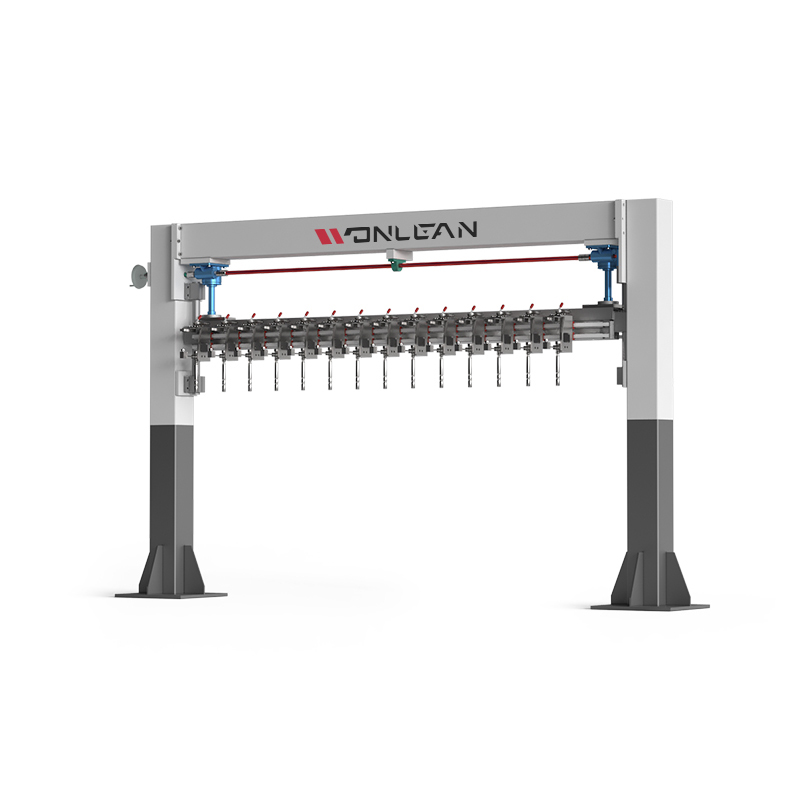
Scaling production often requires more than just increasing feed rates. Deploying a multi-head automatic waterjet cutting system yields massive throughput gains. Adding secondary or tertiary cutting heads to a single gantry multiplies your output. You can cut two or three identical parts simultaneously. This hardware approach is far more effective for high-volume runs than attempting to push a single head beyond its physical limits.
Multiple heads require specific operational upgrades. You must upgrade pump sizing to supply multiple orifices simultaneously. A standard 50-horsepower pump will suffer severe pressure drops if forced to feed too many heads. You need a pump with sufficient horsepower and water displacement capacity, often 100-horsepower or more. Maintaining peak pressure across all cutting heads ensures uniform cutting speeds and consistent edge quality across all simultaneous parts. Water distribution manifolds must be perfectly balanced to prevent pressure starvation at the furthest head.
Glass and brittle materials require specialized speed optimization. An automatic waterjet cutting machine for glass cutting must utilize low-pressure piercing. High-pressure piercing will instantly shatter the glass due to the sudden impact of the water stream. The machine pierces the material at a lower pressure, typically around 500 to 1,000 PSI. Once the hole is established, the system ramps up to high pressure for rapid cutting. The controller must execute these pressure transitions seamlessly to maintain overall cycle speed.
Thick metals and composites present entirely different challenges. Cutting 2-inch steel, titanium, or carbon fiber requires maximum pressure and high abrasive flow. Material thickness exponentially decreases feed rates. The stream loses kinetic energy as it travels deeper into the material. You must slow the traverse speed significantly to allow the stream to clear the kerf at the bottom of the cut. Failure to adjust speed for thickness results in incomplete cuts and severe stream lag.
The industry uses a standard edge quality scale graded from Q1 to Q5. Q1 represents a separation cut. It is fast, rough, and features heavy striations. Q5 represents an excellent, smooth finish. It requires a very slow feed rate. The stream has ample time to erode the material evenly from top to bottom. You must define the acceptable edge quality before setting your cutting speed.
Quality Grade | Description | Relative Feed Rate | Typical Application |
|---|---|---|---|
Q1 | Separation Cut | 100% (Maximum Speed) | Scrap breakdown, rough blanks |
Q2 | Rough Cut | 80% | Parts requiring secondary machining |
Q3 | Standard Cut | 60% | General fabrication, brackets |
Q4 | Good Cut | 40% | Visible edges, moderate tolerances |
Q5 | Excellent Cut | 20% | Precision aerospace, medical parts |
Moving from a Q3 to a Q5 finish requires a significant speed sacrifice. You might have to reduce your feed rate by 50% or more. This trade-off is unavoidable. You cannot achieve a Q5 finish at Q1 speeds. Operators must calculate how much speed they can afford to lose to meet engineering tolerances. Optimizing this balance is key to maximizing daily production yields.
Dynamic articulating heads provide 5-axis cutting capabilities. These heads compensate for V-taper and stream lag. As the waterjet cuts, the stream naturally trails behind the cutting head. It also creates a V-shaped kerf, where the top of the cut is wider than the bottom. Articulating heads tilt the nozzle slightly to offset this taper. This leaves a perfectly square edge on the finished part.
This technology introduces a specific trade-off. Articulating heads improve edge squareness at higher speeds. However, the complex motion control required to articulate the head can slightly increase overall cycle times. The machine must calculate and execute multi-axis movements simultaneously. This process is inherently slower than straight 2D cutting. You must weigh the benefit of a taper-free edge against the slight reduction in overall machine speed.
Running pumps at ultra-high pressures maximizes cutting speed. However, 90,000 PSI introduces severe fatigue on internal components. High-pressure seals degrade faster. Check valves experience extreme stress. High-pressure tubing is subjected to intense expansion and contraction cycles. Pushing the machine to its absolute pressure limits accelerates component wear significantly.
You must factor this wear into your production planning. Faster cutting speeds generate more parts per hour. But they also shorten the lifespan of consumable pump parts. Operators must monitor seal integrity closely. Ignoring preventative maintenance at these extreme pressures leads to catastrophic component failure. Balancing peak speed with component longevity ensures stable, long-term operation.
Pushing maximum abrasive flow rates to achieve top speeds presents physical limitations. Garnet is a consumable abrasive that breaks down upon impact. If you force too much garnet into the mixing tube, the particles smash into each other before they even exit the nozzle. This turns the abrasive into useless dust.
You must calculate the exact flow rate where cutting speed peaks. Pushing past this point wastes material and clogs the delivery lines. A clogged line stops the cutting process entirely. The operator must halt the machine, clear the blockage, and restart the program. This downtime negates any speed advantages gained by increasing the abrasive flow.
Pushing a machine to its absolute speed limits impacts overall uptime. Operating constantly at maximum capacity increases the probability of unplanned maintenance. A blown high-pressure line halts production immediately. A clogged mixing tube requires operator intervention. These interruptions destroy the throughput gains achieved by cutting faster.
Aggregate monthly throughput matters more than peak hourly speed. A machine running reliably at 85% capacity often produces more parts per month than a machine pushed to 100% capacity that frequently breaks down. You must prioritize cutting uptime over absolute top speed. Consistent, reliable operation yields predictable production schedules. It prevents bottlenecks in downstream manufacturing processes.
Evaluating waterjet cutting speed requires looking past brochure linear speeds. You must focus on acceleration, pump pressure, controller processing power, and software kinematics. These dynamic factors dictate actual floor-to-floor cycle times. Raw traverse speed is meaningless if the machine cannot accelerate into corners or maintain consistent stream velocity.
Match your primary part geometries, material densities, and volume requirements to the right hardware configuration. Intricate parts require high-acceleration linear drives. High-volume production benefits immensely from multi-head systems. Thick metals demand ultra-high-pressure pumps. Aligning your machine specifications with your actual applications prevents costly procurement mistakes.
To ensure you select the correct system for your production needs, follow these next steps:
Compile a representative sample of your most common CAD files, including both intricate profiles and straight-line cuts.
Request a documented time study from the equipment manufacturer based on your specific materials and required edge quality (Q1-Q5).
Demand a physical test cut to verify actual cycle times, corner acceleration, and edge squareness.
Evaluate the pump sizing requirements if you plan to utilize multiple cutting heads simultaneously.
A: Yes, higher pressure increases the velocity of the water stream. This higher kinetic energy accelerates the abrasive particles faster, resulting in quicker material erosion and significantly faster cutting speeds.
A: Linear speed is the maximum velocity the machine can reach in a straight line. Acceleration is how quickly the machine reaches that speed and how fast it can slow down for corners. Acceleration dictates actual cycle times on complex parts.
A: Higher edge quality requires slower cutting speeds. To achieve a smooth Q5 finish without striations, the machine must move slowly enough for the stream to erode the material evenly through its entire thickness.
A: Pure waterjet cutting is vastly faster because it cuts soft materials without the restriction of mixing abrasive. The exact speed difference depends on material density, but pure water often cuts hundreds of inches per minute faster.
A: Thicker glass requires exponentially slower feed rates. The water stream loses energy as it penetrates deeper. The machine must slow down to ensure the stream clears the kerf completely without causing internal fractures.
A: Stream lag occurs when the bottom of the waterjet stream trails behind the top of the stream as the head moves forward. If you cut too fast, excessive lag causes incomplete cuts and severe corner wash-out.